
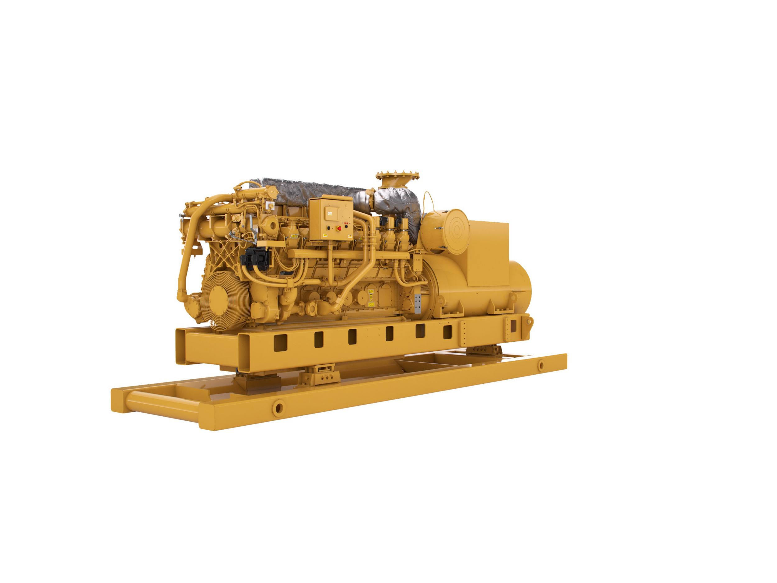
Offshore Drilling and Production Generator Sets
3516C (HD) CI/D2 Hazardous Location
-
Minimum Rating2625 kV·A
-
Maximum Rating2625 kV·A
-
EmissionsEPA Tier 2, IMO Tier II
-
Oil Change Interval1000.0 hr
Engine Specifications
- Minimum Rating
- 2625 kV·A
- Maximum Rating
- 2625 kV·A
- Emissions
- EPA Tier 2, IMO Tier II
- Oil Change Interval
- 1000.0 hr
- Aspiration
- Dual Turbocharged-Aftercooled
- Fuel System
- EUI
- Stroke
- 8.5 in
- Bore
- 6.7 in
- Displacement
- 4760.0 in3
- Engine Control
- ADEM A4
- Weight
- 38581 lb
- Aspiration
- Dual Turbocharged-Aftercooled
- Bore
- 6.7 in
- Displacement
- 4764 in³
- Fuel System
- EUI
- Stroke
- 8.5 in
Dimensions
- Length
- 264.0 in
- Height
- 100.0 in
- Width
- 78.0 in
- Height
- 99.8 in
- Length
- 264 in
- Width
- 78.2 in
Capacity for Liquids
- Cooling System
- 62.0 gal
- Lube Oil System
- 107.0 gal
- Cooling System
- 62 gal (US)
- Lube Oil System
- 107 gal (US)
-
AIR INLET SYSTEM
- Aftercooler core, corrosion resistant (air side)
- Air cleaner, regular duty with service indicators
- Dual turbochargers, rear mounted
-
CONTROL SYSTEM
- Dual Caterpillar A4 electronic engine control with electronic unit injector fuel system and rigid wiring harness.
- 24 VDC (less than 10A) to be provided by customer at Power Distribution Panel to power engine electrical system.
-
COOLING SYSTEM
- Jacket water (JW) engine cooling and two-stage jacket water/separate circuit (SCAC) charge air cooling
- To ensure compliance in use, radiators or heat exchangers must be capable of rejecting sufficient heat to allow proper engine operation at worst site conditions.
- The radiator or heat exchanger must supply 48C (118 F)
- SCAC cooling water to the aftercooler inlet of at least 200 gal/min at ambient temperature of 30C and at site conditions (including altitude considerations)
-
EXHAUST SYSTEM
- Dry gas-tight exhaust manifolds with heat shields, dual turbochargers with water-cooled bearings and heat shields.
- Exhaust outlet: 305 mm (12 in) round flanged outlet, vertical orientation
-
FLYWHEELS & FLYWHEEL HOUSINGS
- Flywheel, SAE No. 00, 183 teeth Flywheel housing, SAE No. 00
- Flywheel housing, SAE No. 00
- SAE standard rotation
-
FUEL SYSTEM
- Duplex Fuel filter, LH service. Simplex fuel filter, RH service
- Fuel transfer pump
- Fuel priming pump, RH
- Electronically Controlled Unit Injectors
- Customer connection located at lower right front of engine
- SOLAS shielding
-
INSTRUMENTATION
- Engine mounted instrument panel with four position switch, over speed shutdown notification light, emergency stop notification light, graphical display unit for analog or digital display of: oil and fuel pressure, oil and fuel filter differential, system DC voltage, exhaust and water temperature, air inlet restriction, service meter, engine speed, fuel consumption (total and instantaneous)
-
LUBE SYSTEM
- Top mounted crankcase breather, RH oil filter, RH oil filler, gear type oil pump, deep sump oil pan, recommended use of Caterpillar Diesel Engine Oil 10W30 or 15W40
-
MOUNTING SYSTEM
- Mounting rails and isolation system based on customer request
-
ELECTRICAL SYSTEM
- MCS certified Class I / Divison 2
- Low Smoke Zero Halogen Wiring Harness
-
PROTECTION SYSTEM
- A-III Electronic Monitoring System provides customer programmable engine de-ration strategies to protect against adverse operating conditions
- Emergency stop push button (located in Electronic Instrument Panel) Safety shutoff protection for oil pressure and water temperature, over speed protection
-
HAZARDOUS LOCATION
- Only electrical system is hazardous environment certified
- NEC 500 Class I Division 2 for gas groups C and D
- Temperature class is T3 for ambient temperatures from -10 C to 50 C
- Class I/ Division 2 CMPD
-
GENERATOR AND GENERATOR ATTACHMENTS
- Class I / Division 2 designed to customer's specifications
- Insulation for harsh environment protection